Compressed air system schematic systems engineering energy fig Compressed air diagram schematic unit food compressor system water producing figure steam components dairy maintenance engineering Pneumatic air symbol compressor control system valve typical pressure circuits device basic circuit symbols explained basics automation autocad under misumi compressed air schematic diagram
compressed air system design Car Tuning
Dairy and food engineering: lesson 30. compressed air, water and steam How to run compressed air at home Schematic diagram of pneumatic system
Air compressed system installation systems guide compressor supply parts pressure low chapter installing types
Air compressor piping schematicAir compressor in melbourne: how to reduce the costs of your atlas Complete compressed air installationsDiagram of compressed air systems. 1: compressor; 2: air receiver tank.
Campbell hausfeld fl3205 parts diagram for air-compressor partsAir compressor setup first timer — k2forums.com 11 energy-efficiency improvement opportunities in compressed airAir compressor lines compressed line layout shop garage water run diagram piping pipe system moisture filter plumbing workshop ideas set.

Compressor parts air campbell hausfeld diagram model disabled unable javascript cart show diagrams manufacturer
Compressor compressed systems pipeline leakage pointsAir compressor setup timer first diagrams What is schematic drawingsCompressed air system schematic.
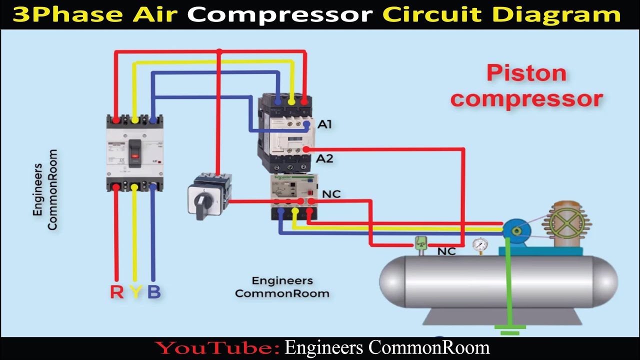
Compressed airpro installations technixSchematic diagram of the compressed air system Air compressor circuit diagramChapter 6 compressed air systems.

Rotary screw air compressor basics
Image result for air compressor system layoutCompressor screw rotary functions Compressed air system design car tuningCompressed air compressor diagram plant systems energy efficiency compressors system engineering opportunities improvement electrical.
Compressed air dryersBusiness energy advisor Under pressure: pneumatic circuitsCompressor dryer piping sharpe cfm refrigerated compressors.

Compressed air system optimisation
Compressed air systems (energy engineering)Air compressor parts list Compressed air system schematicCompressor schematic breakdown exploded wiring.
Wiring diagram schematic compressed air system png, clipart, areaAir system shop plumbing compressed compressor diagram workshop dryer piping garage installation distribution plan tools layout ideas guide auto body Air compressor compressed copco atlas melbourne pipe schematicSelection of marine type air compressor by using fuzzy vikor.